Commodore C64 - Pallet warehouse
Introduction
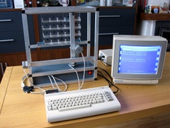
 This article is about controlling a pallet warehouse with the help of a Commodore C64. The pallet warehouse is a part of the educational TibbLto project. The pallet warehouse has 3 stepper motors to move the pallets in the X, Y and Z directions. The Commodore C64 controls the pallet warehouse via the user-port. The program is written in BASIC and machine-code. The pallet warehouse is controlled with 5 inputs.
Pallet warehouse controlled with a Commodore C64
On these Youtube videos you can see the pallet warehouse in action. The pallet warehouse is controlled with a Commodore C64. A C64 was chosen, but a VIC-20, C64, C128, Plus/4 or a Amiga is also possible.
Link
Link
Schematic
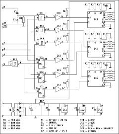
 The pallet warehouse is a "of the shelf" product. It has two connections, one for the power supply (230 VAC) and one for the data (25 D-SUB). Inside there is a printed circuit board with the electronics for controlling the stepper motors. On the picture on the right you can see the schematics. Click on the picture for a bigger version of the schematic.
The simplified working of the schematic is as follows.
The lower part is the power supply that delivers two voltages, about 15 VDC for the stepper motors and 5 VDC for the IC's.
IC4, 5 and 6 are for the controlling of the stepper motors. Pin 3 is for the direction, left or right, of the motors. If there is a pulse on pin 15 the motors will turn one step.
The direction of the motors is "remembered" by IC2. The outputs of the IC are set by the chosen direction on the data-inputs 2, 4 en 6 and a clock pulse on data-input 9.
Which motors will turn is selected by the data-inputs 2, 4, and 6 in combination with pulses on the data-input 8.
The "drivers" of IC3 are used as a interface between the 5 VDC IC's and the 15VDC IC's.
The question is why is the schematic so complicated? You could connect the inputs of IC4, 5 and 6 via the "drivers" from IC3 directly to the user-port. The controls would be even more flexible. The reason I can think of is that in the original design there would be 3 zero-position switches. Then the total number of inputs, including the existing 5 would be 8 inputs. And that would be the maximum number of IO on many computers.
Remark: On the IC's 4, 5 and 6 a heat-sink is installed.
The program
 To control the pallet warehouse software is needed for the Commodore C64. The choice was made to write the main program in BASIC and a small part in machine code.
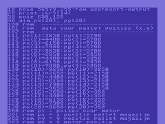
Click on the picture to view the whole program.
The position of the stepper motors is unknown when the system is switched on. The first part of the program can be used to “calibrate” the stepper motors. First the motor Z is driven towards the “zero” position. When the motor stops (mechanically) you press a key on the keyboard. The motors X and Y are calibrated in the same way.
All pallet positions (1-20) are stored in the program, with the number of pulses the X and Y stepper motors need to reach that position from zero.
For driving a motor you need to select the direction and enable the motor. The number of pulses are calculated and poked into memory by the BASIC program. The machine code program is called and it generated the number of pulses for the user port. For placing and retrieving a pallet a small sub-routine is used.
Outputs:
Address = 56577
Bit 0 = Motor - X
Bit 1 = Motor - Y
Bit 2 = Motor - Z
Bit 6 = Motor direction (in combination with Bit 0, 1 and 2)
Bit 7 = Motor steps (in combination with Bit 0, 1 and 2)
The BASIC and MC program in d64 format.
Update: 2019-05-12 13:23:22