Asuro Robot
Introduction
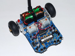 The Asuro robot is a small in C programmable robot. The robot comes as a kit and has the following features: AVR microcontroller, two drive-motors, two signal LEDs, two odometer sensors, a line follow sensor, six collision switches, a status LED and a serial communication (infra-red) with a PC.
A comprehensive manual is supplied to assemble the Asuro robot. But take a look at "My modifications to the Asuro robot" before assembling the Asuro robot.
Development environment
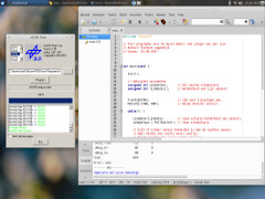 The Asuro robot comes with software for writing the programs for the Asuro robot and for flashing the AVR microcontroller on the Asuro. The software is a little bit old (2003).
For myself I installed a development environment on a Linux system. I use Genie for writing the programs. These are being compiled with the gcc compiler that is supplemented with avr-gcc. For the flashing I use the Windows version of the flash program via Wine. This because the supplied Linux version is no longer usable on a modern Linux system due to its age.
For the communication with the Asuro robot via the USB infrared transceiver I use the program CuteCom.
There is also an alternative flash program for Linux: AsuroFlash
Click here for a manual to install a development environment for the Asuro robot on a Linux system.
My modifications to the Asuro robot (1)
 After assembling the Asuro robot I have tested the sensors. I wrote a small program that continues sends the data from the odometer sensors and the line follow sensor via the infrared transceiver to the PC.
Odometer sensors:
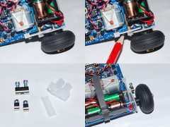
Problem: The gear with the odometer reflection sticker has a lot of play (about 3 mm).Gear on minimum distance (0 mm):
Motor left, white surface: 862, black surface: 476
Motor right, white surface: 915, black surface: 675
Gear on maximum distance (3 mm):
Motor left, white surface: 885, black surface: 642
Motor right white surface: 937, black surface: 804
Modifications:
I moved the four axles of the Asuro robot 3 mm to the outside to make space for a locking system on the axles that have the gear with the odometer reflection sticker. On the axles with the wheels I installed small spacers to correctly align the gear and wheel. The locking system is made from a screw terminal.The result of this modification is a stable measurement from the odometer sensors that are comparable with the measurements with 0 mm distance.
My modifications to the Asuro robot (2)
Line follow sensor:
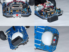
Problem: The surrounding light has influence on the line follow censor.The line follow sensor is a light source that shines its light downwards and two light dependent sensors that receive the reflected light from the surface. I did two measurements, one normal and one when the Asuro robot was covered with two hands.
Normal:
Sensor left, white surface: 970
Sensor left, black surface: 262
Sensor right, white surface: 912
Sensor right, black surface: 298
Covered:
Sensor left, white surface: 600
Sensor left, black surface: 160
Sensor right, white surface: 514
Sensor right, black surface: 146
The following of a line is based on the difference between the two light dependent sensors, for this the absolute values are not that important.
But I also want to recognise a crossroad. The crossroads have a grey colour. I want to link a certain grey to an absolute value of the light dependent sensors.
Modifications:
I built a small shroud around the line follow sensor. This shroud is an old cap from a 9-pin SUB-D connector, from which I removed the top half. De distance between the shroud and the surface is minimal (about 0,5 mm) and that's why the surrounding light has no more influence.With the shroud:
Sensor left, white surface: 520
Sensor left, grey surface: 375
Sensor left, black surface: 91
Sensor right, white surface: 440
Sensor right, grey surface: 310
Sensor right, black surface: 70
The result of this modification is a dependable measurement for white, grey and black.
My first program for the Asuro robot
This is a video of my first program for the Asuro robot. The program uses the line follow sensor to stay on the black line.
My modifications to the Asuro robot (3)
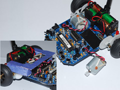 After experimenting with the Asuro robot for a while there was a problem. Strange things happened during the execution of a program, and also the program stopped for an unexplained reason.
I wrote a program that controls the motors and LEDs with the switches. I started testing the Asuro robot and the problem happened when the left motor was turning, but not always.
After I had removed the motor from the circuit board the problem was gone. My conclusion is that the metal cover of the motor caused a short-circuit on the circuit board. I placed a piece of isolation tape on the circuit board and the problem is solved. An extra advantage is that the isolation tape is much less slippery and the motor stays on its place much better. I also applied this to the right motor.
I also made a cover for the odometry sensors. When there is strong sun-light the odometry sensors are nor working correctly. This effects the Asuro robot when driving in a straight line or turning. The cover is made of cardboard.
My modifications to the Asuro robot (4)
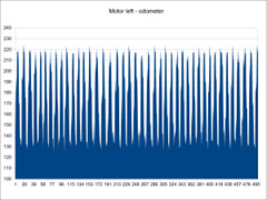 Not every Asuro robot is exactly the same. This has an effect on the measuring values of the sensors. There are possibilities in the software (asuro.c - v2.61) to correct this. I made the following corrections.
The function: ISR (ADC_vect)
I made a temporary change to asuro.c, in the function ISR (ADC_vect), that sends the value of tmp[toggle] from one of the odometry sensors to the PC. I made a graph of these values and this helps to determine the best switch values. My values are < 190 and > 200.The function: Go()
I use the 6 + 6 reflective sticker on my Asuro robot. I wrote a small program that makes the Asuro robot drive forwards for 200 mm. In reality this was not 200 mm.A small correction in the function Go() solved this problem:
enc_count=abs((100L * distance) / 200L);
The function: Turn()
After that I wrote a small program that turns the Asuro robot 180 degrees. A small correction in the function Turn() now takes care of a correct turn:enc_count=abs(degree)*0166L;
The function: PollSwitch()
I also wrote a small program that sends the value of the switches on the Asuro robot to the PC.I have changed the standard value of 61 to 63.
The function: LineData()
After that I wrote a small program that sends the value of the line follow sensor on the Asuro robot to the PC. There was a difference between left and right of 20%.A small correction in the function LineData() has solved this problem:
data[1] = (((ADCL + (ADCH << 8)) * 120L) / 100L);
My second Asuro Robot program
This time a bigger and more difficult track and an obstacle! The program uses the line following sensor to stay on the black line and switches to detect a collision.
The program for the Asuro robot and the track for the Asuro robot.
The program for the Asuro robot and the track for the Asuro robot.
My modifications to the Asuro robot (5)
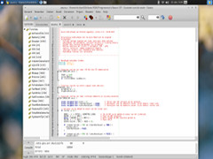 If you write a program for the Asuro robot you make use of the Asuro library, in my case I use the Asuro library v2.61. This library has functions for reading the odometer and line following sensors, you can make turns or ride for a certain distance and much more.
I discovered that the reading of the odometer sensors was disrupted by other functions. If you are getting information from other sensors, the reading of the odometer sensor is halted. This means that the odometer system is not very reliable when following a line.
I decided to make a personal Asuro library based on the Asuro library v2.61. The major differences are:
Odometer sensors and line following sensors are now read continuously and the values of the sensors are continuously available as global variables. The odometer counters are also continuously updated and are also available as global variables. Every 1 ms one of the four sensors is read, so after every 4 ms all the sensor values are refreshed.
The motors are now controlled by only variable per motor. The range is from -255 to +255, the minus means reverse speed, positive is forward speed and the motor breaks when the value is zero.
A dedicated interrupt routine for detection of the switches and improved routines for turning and driving with the odometer sensors.
My modifications to the Asuro robot (6)
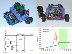 The electronics of the Asuro robot are powered by a battery. You can use four normal or four rechargeable batteries. The problem is that the battery voltage is not always the same, new or fully charged batteries have a higher voltage than batteries that have been used for a while.
The odometer sensors are less reliable when the voltage is low. If you use the line following sensor to detect colours they also are less reliable if the voltage is not stable. And the driving speed is also dependent of the battery voltage.
A solution is to use a voltage regulator. But a standard (linear) voltage regulator uses about 2 Volts to do its job. This means you need more batteries to compensate for the extra 2 Volts, and the efficiency of these voltage regulators is not great.
A better solution is to use a switching voltage regulator. I use a switching voltage regulator that is based on a XL6009 from XLSEMI. But there is a small problem, when the input voltage is between 2.75 Volts and 3.75 Volts, the output voltage is far greater than the normal output voltage. The solution is to make a small circuit that enables the switching voltage regulator only if the input voltage is higher than 4.15 Volts.
With this system the voltage for the Asuro electronics is now always 5.95 Volts when the input voltage is between 4.15 Volts and 6.30 Volts.
The extra switch is necessary because the switching voltage regulator is always working, and will drain the battery.
My modifications to the Asuro robot (7)
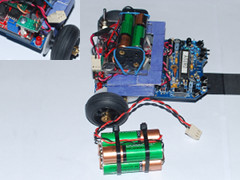 More power… The Asuro robot is powered by four normal or four rechargeable AAA batteries. My rechargeable AAA batteries have a capacity of 900 mAh. I wanted a little bit more than that and decided to upgrade the battery system.
First I installed a simple connector (PCB header) on the Asuro robot. Then I took a small connector (3 pins) from an old PC and connected that to the original battery pack. The connector on the Asuro robot has an extra pin that prevents that the connector from the battery-pack is connected in the wrong way.
I also made a second battery-pack with four rechargeable AA batteries that have a capacity of 1300 mAh. In the future I will make another battery-pack with capacity of 2500 mAh.
The advantage is that I now can use one battery-pack on the Asuro robot and charge the other battery-pack. And swapping the battery-packs is very easy.
The Asuro Robot and a maze
This time the Asuro robot drives through a maze. The Asuro robot learns the maze and can drive the shortest route. If there is an obstacle, the Asuro robot drives an alternative route.
Update: 2019-05-12 13:22:03