Input devices
Introduction
 You can use Commodore computers for about every application. But almost every application has an interaction with the user. For these interactions you need a input device. The most well known is of course the keyboard. But there are also others such as the : joystick, paddle, mouse, touch pad and external keyboards like a piano keyboard. It is also possible to "read" switches or sensors via the different ports but these are not mentioned here.
Input devices have changed in the years. Sometimes only the shape like the keyboard. The mouse traded it's ball for a light what was the best thing ever. In the beginning joysticks had only 5 switches but nowadays you need the manual to learn and use all the options. And the latest fashion is to go wireless.
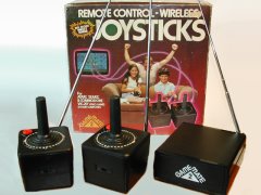
On the picture the Game mate 2 joystick set. This was one of the first remote devices available for the Commodore computers (also for other brands). Each joystick had a battery powered transmitter. And the receiver was connected to the computer such as the C64.
The keyboard.
 The first computer that Commodore brought on the market after taking over the company MOS was the KIM-1. The KIM-1 has a small keyboard with only 23 keys. With these keys the KIM-1 was programmed and controlled. The next generation Commodore computers (PET / CBM) had a much bigger keyboard that looks like that of a type writer. After that the keyboard were extended with function keys or separated numerical keyboards (VIC-20 / C64 / C128). The last generation Commodore computers (Amiga / PC's) had all the bells and whistles on there keyboards.
Many Commodore computers are actually keyboards with a computer underneath. The more expensive models such as the SX-64, C128D and the big Amiga's are equipped with a separated keyboard. There are also a couple of Commodore computers that don't have a keyboard at all like the C64 GS, CD-32 and the C64-DTV.
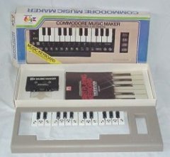
On the picture the Commodore Music maker. This is a simple overlay keyboard for the C64. If you press a key on the piano keyboard you actually press one of the keys of the "real" keyboard. The program translates the keys to music notes or music effects.
Keyboard technique.
 How does a keyboard work? If you count the number of keys on for instance a C64 than you will come to 66 keys. If you count the 2 joysticks with each 5 "keys" then the total will be 76 keys (or inputs). Normally you would need a chip with at least 76 inputs to read all the signals (keys). The computer industry is known to design as smart (read cheap) as possible. The trick which is used in almost all keyboards is "keyboard scanning". Scanning is reading data at one input at the time. With this technique you can read a keyboard of a VIC-20 or a C64 with only 2 x 8 = 16 inputs.
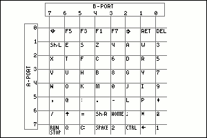
On the picture you can see the keyboard matrix of the C64. It is constructed of a grid of wires. And it has 8 wires horizontal and 8 wires vertical. On each crossing there is a switch connected (the keys). The wires on the left 0 - 7 are connected to the A-port of the CIA and writes the rows. The wires on the top 7 - 0 are connected to the B-port f the CIA and reads the columns.
Now how it works. If the computer does a scan the A-port of the CIA is switched to WRITE (output) and the B-port to READ (input). The computer puts the number 0 on the A-port. (binary this is 0000 0000). If the inputs of the B-port are not connected to anything each input will read a "1". Next the B-port is read. If this is not equal to 255 (1111 1111) there is a key pressed somewhere in the matrix. The number on the B-port is for instance 1111 0111. The key that could be pressed is F7, 4, 6, 8, 0, -, HOME or 2. When it is established that a key is pressed and which column this was the the next scan will be done. In this second scan one of the 8 bits of the A-port will be made a "0" and the rest will be "1". Each time the "0" on the A-port will be moved to the next bit. When the B-port reads a number not equal to 255 (1111 1111) the right row is found. If bit 6 of the A-port was "0" than the pressed key was "HOME".
But now for the people who can count. In the matrix you have 8 x 8 = 64 possibilities. But there are 66 keys. How is that possible? The SHIFT-LOCK key is a key that stands parallel to the left SHIFT key so this is not a separate key. The key that remains is the RESTORE key. The RESTORE key has it's own connection via some electronics to the CPU on the NMI input.
But the joysticks also have 2 x 5 = 10 "keys". The joystick signals are also connected to the matrix. Maybe you have noticed sometimes that if you move the joystick some characters appear on the screen. How can you see if the depressed key is one of the keyboard keys or a joystick switch? If you set the number 255 (1111 1111) on the A-port and if you read something else on the B-port then 255 (1111 1111) it will be a switch from the joystick. The joystick will ground the column to GND so what ever you will do with the keys the bit on the B-port will always read "0".
Another trick is that you can read more than one key at the same time. For instance SHIFT and F1 (=F2) together is possible because they are in a separate column and can be read right after each other.
Other Commodore computers will do the more or less the same. The C128 has 11 inputs in stead of 8 and can read more keys. The Amigas and the PCs have a keyboard that has a complete keyboard scanner build in. This scanner sends a code to the computer when a key is pressed. The computer can also send a code back to turn on or off the LEDs on the keyboard.
The joystick.
 In the early arcade game computers joysticks were installed to control the game. The CBM / PET series was meant to be a serious computer and did not have a connection for a joystick. But later the user port was used to connect joysticks.
The VIC-20 computer was much more usable for games then it's predecessors and had standard a connection for a joystick. This was the digital joystick. Digital means that there are only 2 possibilities for each channel (bit). So a bit can be a "1" or a "0". The joystick port has 5 of those channels (bits) and can read the following signals Up, Down, Left, Right and Fire.
The counterpart of the digital joystick is the analog joystick. This one has two analog channels and 1 or more digital channels. The analog channels are normally adjustable resistors. The computer reads the value of the resistor and can determine the position horizontal and vertical. The digital channel is used for the fire button.
Commodore has always used the digital joysticks. The successors of the VIC-20 even have 2 joystick connections as standard.
There are made more than a hundred different joysticks that could be used for the Commodore computers. From really bad to excellent. A example of a really bad one is the Commodore 1311. The switches that were used inside were really bad. If you would play a game such as Decathlon the joystick would probably break before you finish the game. The top of the range joystick were made by the company SUZO (the Netherlands). This company made the world famous Competition Pro and the Arcade joysticks. This company made joysticks for arcade cabinets and they had to be extreme durable. The Competition Pro and the Arcade are derived from those arcade joysticks. The in 2004 released C64-DTV looks are based on the Competition Pro.
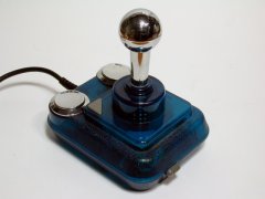
On the picture the Competition Pro in its transparent deluxe version. This joystick has autofire and slow-motion. This joystick is very durable and has micro-switches.
Joystick technique.
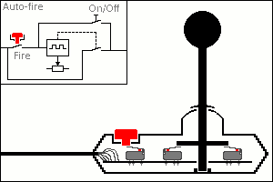 The technique inside a joystick is very simple. The signals come from five switches. For the directions up, down, left and right you will need 4 switches and one more for the fire button. On the picture you can see a view of a SUZO Arcade joystick. The stick is made from plastic but there is a 6 mm thick core inside to prevent bending of the stick. The bottom of the stick is placed in a tilting point. In the middle the stick is kept in the center by a centering device. Just above the micro switches there is a big round disk. If you push the stick in a direction one (or two) micro switches will be pressed.
The deluxe joysticks are also equipped with a so called auto-fire. Auto-fire is a system that automatically presses and releases the fire button in rapid order. In the top left corner a block diagram can be seen of the auto fire system. On the left there is the fire button. When the fire button is pressed a electronic system is activated. This system will produce a pulse train. The pulse train is connected to a electronic switch which is connected to the fire input of the computer. The rate of fire is sometimes adjustable and there is also a on/off switch for the auto-fire system.
Another feature is slow-motion. This works a little bit like the auto-fire system. But now it does not press or releases the fire button in rapid order but it disconnects and connects the directions in rapid order. With this function it looks like if you are controlling the stick very gently by putting the stick in the center position for a short period.
Other features are stopwatches so you can see how fast you can play the game. The legendary German magazine 64'er has published a system that could store the joystick movements in to a memory. If you want to skip a level you just start the memory and all the joystick movements were repeated.
Because the joystick is connected to the keyboard matrix the signals of the joysticks are read in the same way as the keys on the keyboard (see the previous part). Because the double function of the keyboard and the joysticks it could be that a program gets into trouble if you use the joystick. Most of the time the joystick port 2 was used because that caused the least trouble.
A unknown fact is that the joystick connections can not only be read but also be written. This means you can control devices that are connected via the joystick connector. But the User port is much better at this so the use is limited.
The Paddles.
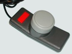 The Commodore TV-games 2000K and the 3000H are equipped with adjustable controls. This are adjustable resistors and the are changed in value by rotating or sliding. The first games for the TV were based on PONG. The control was done by paddles.
The VIC-20 is also suited for these paddles. The remarkable fact is that they come a set of two and share the same connector. The C64 has two 2 joystick ports and it is possible to connect four paddles at the same time.
But the number of games for paddles is limited and the popularity of the joystick didn't help either.
On the picture the Commodore 1341 paddle.
Paddles technique.
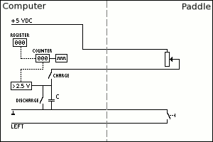 The paddle itself is a simple device. The device is made of a adjustable rotating resistor. If you turn the knob all the way to one side the resistor value is about 200 ohms and if you turn it all the way to the other direction the value is about 200 kilo-ohms. Also each paddle has a fire button. But because the paddles are both connected to the same joystick port the fire button cannot be connected to the normal fire input. One of the paddle fire button is connected to Left and the other to Right.
The system inside the computer that reads the paddle is much more complicated than the paddle itself. The reading inside a C64 is actually a task of the SID-chip (The music chip). In the picture you can see a block diagram of the reading system.
To read a value (position) the following will happen:
The counter is put on zero.
The charge switch is closed.
A pulse train will let the counter count from 0 to 255.
A trigger system looks continuously at the voltage over the
C (capacitor).
The capacitor will be charged because a current will flow from the 5 volt through the resistor into the capacitor. (voltage over the capacitor will increase)
When the voltage over the capacitor reaches 2,5 volt the output of the trigger will give a signal to the counter.
The counter copies it's value to the register.
The charge switch is opened and the discharge switch is closed and will bring the voltage over the capacitor to zero.
The system is now ready to read the next value.
If the resistor has a low value the charge current is high and the capacitor will be charged quickly. The counter only just started counting and the value that is copied to the register is about 0.
If the resistor has a high value the charge current is low and the capacitor will be charged slowly. The counter is counting for a while and the value that is copied to the register is about 255.
In the real world the number of possible positions of the paddle is not 0 to 255. A number of technical reasons limit the maximum resolution to about 225 different positions. The SID has two of these reading systems and can read 2 paddles at the same time. To read all four paddles the SID has a nice trick. Inside a C64 is a double analog switch that can be controlled by the SID. The SID switches first to the paddles on joystick port 1 and after reading the values it switches to the other joystick port to read the other 2 paddles. With a Machine Code program you can watch the SID when it's switches and so you can use all four values.
The Mouse.
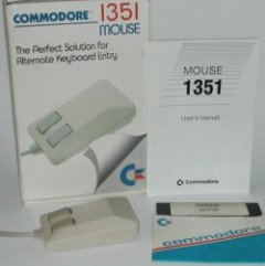 Every modern PC has a mouse. But the mouse is already more than 35 years old. The mouse was invented by Douglas Engelbart. The mechanism contained two wheels that were 90 degrees shifted to each other. If you pushed the device forward or backward one wheel would turn and if you pushed left or right the other wheel would turn. After a while the famous ball was added.
The mouse got very popular when the graphic operating systems took over the computers. The company Apple started this revolution. Quickly followed by other computer brands like Commodore with the Amiga series and Atari with it's 16-bit series.
The amiga had a mouse to control the whole computer system.
With the introduction of the C64c the software package GEOS was included. GEOS is a Graphic Environment Operating System that is designed to work with a mouse. This was the package that made the mouse popular on the C64.
On the picture the Commodore 1351 mouse. The 1351 can work as a mouse but also as a joystick.
Mouse technique.
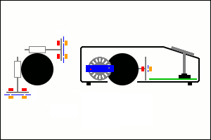 The mouse is made of a ball with two censors and a couple of switches. The censors are rollers that are connected to a slotted disk via a shaft. The whole thing is mounted in such a way that it rotates very easily when the ball moves. If the ball moves the slotted disks will rotate. The rollers are placed in a way that if you move backward or forward one slotted disk rotates and if you move left or right the other disk rotates. If you move diagonal both slotted disks will turn. Most of the times there is a third roller that ensures that the ball is pushed firmly against the rollers.
On the picture you can see a drawing of the inside of the mouse. On the left is a top-view and on the right is a side-view. The black object is the ball. Against the ball are the rollers. The rollers are connected to the slotted disks. The red blocks are the infra-red LEDs and the orange blocks are the infra-red censors. The blue part is a mask. The green part holds the electronics and the switches of the buttons.
Now how it works. On one side of the slotted disk there are two infra-red LEDs. A infra-red LED emits non visual light. The light goes through the disk or hits the disk on the fact if there is a slot for the LED or not. On the other side of the disk is a mask with two little holes. At the other side of the mask two infra-red censors are placed. These infra-red censors react when they see infra-red light through one of the slots and the hole in the mask. The reason to use infra-red light is that normal (day-) light that gets into the mouse will not interfere with the censors.
If the ball moves or not the electronic can see that with the infra-red censors. To see which direction the slotted disk is turning it compares the two sensors with each other. The two holes in the mask are not at the same height. So if the slotted disk is turning, one infra-red censor will see the light earlier or later than the other censor.(depending on the direction of rotating). The electronics looks when one infra-red censor switches of (no more light) and looks at the other infra-red censor. If the other infra-red censor is on (it sees the light) the disk is turning in a direction and if infra-red censor is of ( it doesn't see the light) the slotted disk is turning in the opposite direction. The distance that the ball moves is related to the number of times that a slot is passing the infra-red censor.
The mouse has also a resolution. The resolution is higher if the number of slots in the disk is higher. The resolution is also dependent of the relation between the diameter of the ball and the rollers.
The mouse has two or more buttons. These are connected to the (digital) joystick inputs. The position of the mouse (x-y) is transmitted to the computer via the (analog) paddle signals. To know how this works read the part on Paddles.
The PC and Amiga range of Commodore models use a different mouse. The difference is the way they transmit there signals to the computer.
The optical mouse works different to the ball mouse. Inside the optical mouse is a LED that emits a red light. Besides the LED there is also a digital camera inside. This camera continuously takes pictures of the ground were the mouse is placed on. If you move the mouse the pictures will change. The electronic now moves the new picture over the old picture to get a match. The electronics can measure the difference in distance on the picture comparison and send the changed position to the computer.
Because there are no moving parts inside the optical mouse they are much more reliable then the ball mouse. The ball mouse is often not working perfectly because dirt gets into the ball and roller system. The resolution of the ball mouse is limited by using mechanical parts. The resolution of the optical mouse is only limited by the resolution and the speed of the build in digital camera.
The track-ball.
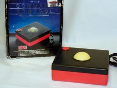 A competitor of the mouse is the track-ball. A track-ball is a up side down version of the mouse. Instead of moving the whole mouse around you only move the ball with your fingers on a trackball.
A advantage of the track-ball is that it stays at the same place so you need less workspace. The ball it self is very different to the ball of a mouse. A mouse has a small rubber ball and the track-ball is a much bigger and hard ball that looks like a pool-ball.
A big disadvantage is that when you are moving the ball with your finger it's hard to keep the button depressed at the same time.
The track-ball is mostly used on control systems were you go to a specific menu or icon and click on it. The track-balls are often used in industrial applications.
Track-ball technique.
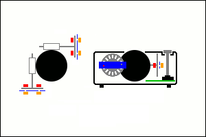 Besides the fact that the track-ball is a up side down version of the mouse the rest is pretty much the same. The bigger ball and housing makes lager slotted disks possible. This will have more slots and thus more resolution. Also the relation diameter of ball and rollers is bigger so also a bigger resolution is possible.
On the picture you can see a drawing of the inside of the track-ball. On the left is a top-view and on the right is a side-view. The black object is the ball. Against the ball are the rollers. The rollers are connected to the slotted disks. The red blocks are the infra-red LEDs and the orange blocks are the infra-red censors. The blue part is a mask. The green part holds the electronics and the switch of the button.
For more information, read the part about the mouse.
The Touch pad.
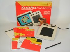 A touch pad is a pressure sensitive surface. The most well known touch pad for the 8-bit computers is the KoalaPad. The KoalaPad was not only available for the VIC-20, C64 and C128 from Commodore but also for the Apple, Atari, Texas Instruments, IBM-PC and many more computers. Nowadays many laptops also have a touch pad to replace the mouse.
If you press with a special pen (stylus) on the pressure sensitive surface the position is send to the computer. The KoalaPad is mostly used in combination with Koala Painter graphical program. There are more of these touch pads made for the Commodore computers such as the Muppet Learning Keys. This was meant to teach children to read and calculate and is made by the same inventor.
On the picture the KoalaPad from the Koala Technologies Corporation. This input device was used in combination with Koala Painter graphical program. This version has the program on a disk.
Touch pad technique.
 The inventor of the touch pad is David D. Thornburg and he did his invention in the year 1982. He worked at Xerox Palo Alto Research Center at this time. He was developing a pressure sensitive input device for computers. Xerox did not see the value of this invention and gave David the chance to develop it further on his own. David started the Koala Technologies Corporation and put the KoalaPad into production.
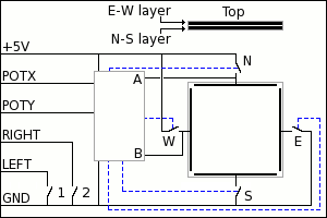
How does it work? The pressure sensitive device consist of the following parts. A sturdy base with above that two layers of electrical conducting material. These two electrical conducting layers are not touching each other. The whole thing is covered by a scratch resistant layer. This is the black part on the picture of the KoalaPad.
On the picture you can see the block diagram of the KoalaPad. The two electrical conducting layers have a connection strip on both sides. In the picture you see all four connection strips but in reality the layers are under each other. When you press with a special pen (stylus) on the top layer you will press the two electrical conducting layers together. On the point you press the two layers make an electrical contact with each other.
But how does the computer knows what the position of the pen is on the pad? In the block were all connection come together is the electronics of the KoalaPad which controls the pad.
The switches N and S are closed. Now there is a voltage over the electrical conducting layer of 5 volts. If you look from the N point the voltage will decrease to 0 downwards to the S point. For instance on 20% of the distance to the S point you will have 4 volt. On 50% of the distance is 2,5 volt and on 90% of the distance only 0,5 volt. Measuring point B is connected to the other electrical conducting layer. At this measuring point you will measure the voltage where the two layers are connected. For instance this is 1 volt and is the position in on the Y axis.
Now the switches N and S are opened and the switches E en W are closed. Now the voltage of 5 volts is from the point W to E. Now the measuring point A measures the voltage on the position where the two electrical conducting layers connect. For instance this is 4 volt and is the position in on the X axis.
The build in electronics turns the measured values (position X-Y) into a pot meter value and sends it through the (analog) paddle input of the joystick port to the computer.
People with a bit of electronics knowledge will say you will always have a fault with your measuring because the layer from the connection strip to the connection point is also a resistor and will vary in value when the distance to that point changes. But the impedance of the measuring is far greater than the resistance of the electrical conducting layer. So you can neglected the measuring fault.
The KoalaPad can only measure 1 contact point at the same time. If you press the surface at more than one place the measured values will be wrong and the position will be wrong also.
The resolution of the KoalaPad is depended of the (analog) paddle input of the joystick port and is about 225 x 225 pixels.
On the KoalaPad there are also two switches that can be used in the KoalaPainter program. These switches are connected to the left and right direction of the joystick port. (Just like the paddles)
Lightpen / Lightgun
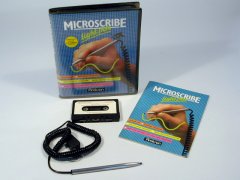 A totally different way to control the computer is with the help of a light pen. To make a choice you simple press on the screen and the computer knows where on the screen you have pressed.
The light pen did not became as popular as other devices like the joystick or mouse. The light gun was more popular thanks to the games were you can shoot at criminals or ducks.
On the picture the light pen from MicroScribe including the software.
Light pen / Light gun technique.
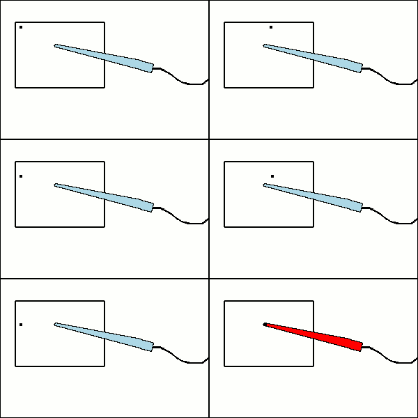 The reason that the light pen works is the VIC-chip (graphical chip inside the VIC-20 and C64). Most of the Commodore computers are compatible with the TV-signal. If you look at the TV-screen you will see a complete picture as large as the screen itself. In reality the screen is "made" by a beam of electrons that "crashes" onto the inside of the screen. A coating on the inside of the screen will light up when it is hit by a electron. The electron beam starts in the upper left corner and "writes" to the right. At the end of the line it goes very quickly to the left and starts at the next line. When the electron beam has reached the lower right corner everything starts all over again. The material that lights up keeps lighting up about the same time as the beam needs get to the same point again. In reality the lines are not "written" one after the other but first all the even lines are "written" and then all the odd lines are "written". This give a better picture but does not interfere with the working of the light pen.
In 1 second the complete screen will be "written" 60 times (50 times for PAL) that is 30 times the odd lines and 30 times the even lines. The screen frequency is thus 30 Hz.
On the picture you can see a light pen. The moving dot is the electron beam. In the tip of the light pen there is a photo-transistor that switches as it sees a light. This light is the electron beam that passes in front of the light pen. This foto-transistor sends a signal to the VIC chip via the joystick port. Because the VIC chip controls the electron beam itself it knows the position of the electron beam at all times. And will put the position of the light pen into a register that can be read by the program. The tip of the light pen has also a normal switch which blocks the signal of the photo-transistor when the pen is not pressed against the screen. This will block false readings when the pen is moved along the screen but not touching it.
The light gun works about the same but there is a lens build in so it can only see a little part of the screen.
External keyboard.
 Most people will know the Commodore Music maker. This is a simple overlay keyboard for the C64. With this Commodore Music maker you can play the piano but it is very limited. After intensive use the keys of the keyboard will get worse and the playing will get worse too. There were made special piano keyboard for the C64.
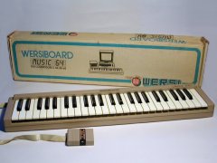
On the picture the WersiBoard. This is a very nice piano keyboard with real keys and is connected to the C64 via the Expansion port.
External keyboard technique.
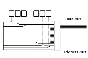 The problem with a keyboard is that it has more than 8 keys. Most 8 bit computers can only read 8 inputs at the same time (16 bit computer 16 inputs). By most keyboards a matrix scanning system is used with for example 2 x 8 inputs. See the previous part on keyboards.
The ports for instance the C64 have a maximum of 8 inputs and to make the matrix you will need at least 2 ports for reading an external keyboard.
The solution inside the WersiBoard is different. On the picture you will see a small part of the complete electronics inside the Wersi-board. The WersiBoard has 4 x 12 = 48 keys. (Only 6 keys are drawn in the picture). Every key has it own connection to the electronics. This electronic will read 8 keys at one time and put there signals on the data bus of the expansion port. With the signal line WRITE the information is written into the memory on address $D000. Before reading the next 8 keys the electronics changes the address bus to the next byte. Then it reads the next key and put that information in the memory at $D001. In this way all keys are scanned and there information is put into the memory.
The music program will translate this information into music notes or music effects. The limit on how much keys you can scan is limited by the available memory were normally a cartridge is (2 x 8 kbyte).
Update: 2011-06-24 19:51:27