Commodore News Page Richard Lagendijk English Nederlands Deutsch Polski CommodoreInfoPage - YouTube mos6502 - Twitter RSS

Portfolio

Introduction

Richard Lagendijk Let me introduce myself, I am Richard Lagendijk and I live and work in the Netherlands. To show what I do, I have put together a portfolio. This portfolio contains a variety of projects that I have carried out in my private life, during my education or during my work.
[583]

Asuro robot

Asuro robot Asuro robot

The Asuro robot is a small programmable robot. The robot is supplied as a kit and features an AVR microcontroller, two drive motors, two signal LEDs, two odometer sensors, a line follow sensor, six detection switches, a status LED and a serial (infra-red) communication option with a PC.

This robot was a part of my bachelor education program. The goal was to let the robot drive in a warehouse, learning the shortest route and dealing with obstacles. To make this assignment possible, I had to improve the capabilities of the robot. The improvement are: Altering the installation of the odometer sensors, so that there is no more variation in the distance between the light source/sensor and the code-wheel. Shielding the line follow sensor from the surrounding light. Enlarging the battery capacity for more range, and regulating the voltage for better performance of the sensors.
I also rewrote 80% of the standard firmware to improve stability and accuracy of the sensors, and I added or improved functions to make programming the robot less difficult.

The end result was a robot that can scan the whole warehouse, determine the shortest route and deal with obstacles on the route.


More information about my Asuro robot project.
[584]

Employability of staff

Employability of staff A team leader from my company asked me if I could visualize the employability of his team for the next ten years. For this I used an Excel file with various functions in VBA (Visual Basic for Applications).

The data is entered using a form to avoid errors. These are the name, position, department, FTE, year of birth, on-call duty, the knowledge level (junior, medior and senior) and the corresponding growth forecast in the knowledge level.

The graphs are generated based on a self-selected starting year. A few examples of the graphs are:

Age structure: start year, next year and the following 10 years, with an age division per 5 years. Number of years in service, number of employees ending employment, number of employees above a certain age.

Knowledge structure: start year, next year and the next 10 years with an age division per 5 years. The knowledge is classified as junior, medior and senior, including a forecast of knowledge growth in the coming years.

Number of employees available for on-call duty and an overview of the number of employees per position in a department.
[585]

Reverse engineering

Reverse engineering the KCS Power cartridge. One of my hobbies is collection everything from Commodore computers. Of course, it is always better to have the real item, but some items are very hard to find. To make old computer items available to everyone, you can build a replica, but first you need to find out how the original was built and how it works.

To make a replica PCB, you need to know where all the copper-traces connect to. For the bottom side, this is not so difficult, you only need to remember to draw the mirror image in a PCB drawing program. I measured all the locations of the holes and via's and drew them in the PCB drawing program. After that, I connected all the copper-traces to the holes and via's.
The upper-side of the PCB is more difficult, because the components are obscuring the copper-traces, but with the help of a multi-meter you can find all the connections.

After that you need to find which components are used, and if there is something like Eprom you need to read the data from this Eprom.

But sometimes the original creators made it very difficult to reverse engineer their product. On the picture is an example of the Power cartridge from KCS. To make it more difficult, KCS erased the text from the components and scrambled the address-lines of the Eprom.

And after many hours to create the PCB, schematic, component list and the Eprom-file it is now possible to create a replica of an old piece of hardware.


More information about my KCS Power cartridge project.

[586]

Collecting data from a public drinking water tap

Collecting data from a public Oasen drinking water tap. The drinking water company where I work has about thirty public drinking water taps in its supply area. The question from the area manager was whether it is possible to gain insight into the use of these public drinking water taps.

The conditions of this project are: The recording of date & time. The logging system must fit into a standard public drinking water tap. A simple system, which is easy to remove or install, but is not visible from the outside. And there is no external energy supply available.

To be able to log the data, a signal is required when someone presses the button on the water tap. First I tried to connect a switch to the existing push button of the drinking water tap. But the push button is not suitable for an additional switch. A second solution was to measure the pressure between the push button and the outflow point as soon as water starts to flow. However, the built-up pressure was too low for a reliable measurement. The third solution uses a flow detector from a central heating boiler.

To record the data, a logger has been chosen that can record a change in a signal (on/off) with the date and time. To protect the logger against the elements, it is placed in a plastic housing.

The logger works on a battery and can collect data for about two years. The logger can easily be disconnected from the electrical wiring (USB plug) and then read with a laptop, for example. The software for reading the logger is provided free of charge by the logger manufacturer.
[587]

Visualizing solar panel information

Visualizing solar panel information The drinking water company, where I work, has a building with a solar panel installation. The question from the organization was whether the information from this solar panel installation could be visualized.

I started collecting information about the existing solar panel installation. The installation consists of 88 solar panels with a SolarEdge energy converter, type SE25K. The energy converter can supply a maximum of 25 KVA to a 3-phase electricity network. Communication is possible via an RS485 or an Ethernet connection, the communication protocol is Modbus.

After the Ethernet connection was connected and set up, I started investigating via Node-RED what information can be obtained from the SolarEdge energy converter. There was a register map available, and after determining whether it was Modbus base 0 or base 1 it was possible to read out the voltage and current (DC). Some research was still needed to find out how the scaling factors of the measurements worked.

I then wrote a complete Node-RED flow for retrieving, processing and storing all information from the SolarEdge energy converter. For the visualization and control of the information, I created a dashboard in Node-RED. For the presentation of the data for internal use, I created a dashboard in Schneider Electric's PME. Reporting in Power BI from Microsoft is also available.
[588]

Teach-robot documentation

Teach-robot documentation Teach-robot documentation

The Teach-Robot is a robot with six axes and is intended for educational purposes. The Teach-Robot is about 60 cm high and is made up of glass fiber reinforced plastic parts and six actuators. The actuators are controlled with a bus system. The control of the Teach-Robot is possible via the Teach-Box or with the Teach-Robot Studio software.

The documentation of the Teach-Robot is limited, and the technical knowledge about the Teach-Robot is known by a very small group of people. The limited documentation poses a risk to the continuity of the product.

For this project I wrote two assembly manuals (Teach-Robot & Teach-Robot Plus). These manuals describe the entire assembly step by step with text and images, including assembly sequence, parts used and practical tips during assembly. The correct adjustment, testing and packing of the Teach-Robot is also described. A complete parts list is also available for assembly, which can be used for collecting the parts for assembly and for inventory management.

A separate manual is available for programming the microcontrollers in the actuators in the Teach-Robot and the microcontroller in the Teach-Box. This is because in practice the assembly and programming is often carried out by different people.

There is also a manual for troubleshooting the Teach-Robot and Teach-Box, in which I have described all my knowledge that I have gained during the repairs to the Teach-Robot and Teach-Box.

Two manuals are available for the user, for using the Teach-Robot and Teach-Robot Studio.

[589]

Jutter Pro

Jutter Pro A number of drinking water companies in the Netherlands use groundwater from extraction wells to prepare drinking water. An extraction well is a pipe that goes perpendicularly into the ground from ground level to an sand aquifer. In the sand aquifer, this pipe is fitted with a filter that allows the water to pass through, but not the sand. The water flowing to the extraction well contains small contaminants that, over time, clog the filter of the extraction well. These contaminants on the filter are removed again during the jutter proces.
The jutter proces is the constant movement of the water level in the extraction well. The lowering of the water level is done with compressed air and the raising is done by the natural pressure of the water in the aquifer. After a certain jutter time, the contamination has been removed from the filter and the extraction well is again available for the extraction of water.

For this project I designed the entire installation, built it mechanically, installed it electrically, programmed the PLC and the Scada, tested it and put it into operation. After that, together with the users, I further developed the jutter installation into the current version.
A complete technical file has been created, with construction drawings, electrical diagrams, PLC/Scada software, parts list, user manuals and standard settings.

A SAIA PCD with a touch-sensitive operating screen and a modem have been chosen for the control system, so that local and remote control is possible.

The control consists of several screens for operation, setting values, retrieving historical data / graphs and viewing status and error messages. The operating screen displays the current values of the water level, pressure, jutter speed, status of the valves, jutter times and any error messages. The jutter process is fully adjustable: jutter methods, water levels, pressures, times, alarm levels, etc.
When operated remotely via telephone, laptop or tablet, full functionality is available, and it is possible to send status and alarm messages to the user via SMS.

[590]

C64 DTV

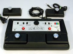
C64 DTV The C64 DTV is a game console in the shape of an old joystick. But this game console is actually a complete Commodore C64 computer with 30 games. DTV stands for Direct-to-TV. What means that you can connect the C64 DTV directly to your TV and you don't need any other hardware or software to play the games.
The C64 DTV is designed by Jeri Ellsworth after she developed the C-one. The C-One is a replacement for 8-bit Commodore computers based on FPGA technology.

You can use the C64 as a normal game console, but it has a lot of hidden secrets. For technical people like myself, it is possible to "hack" the C64 DTV to use the extra options that are hidden from the normal user.

The first C64 DTV that I modified is based on the NTSC version and is built together with a Commodore 1571 disk drive and a normal PC keyboard. With this setup you can use original disk drives and printers, two external joysticks and a keyboard. When the PAL version was available, I also modified this version.

I also modified C64 DTVs for other people. One example is a C64 DTV that has all the modifications inside the C64 DTV itself. This one also has a 1541-III inside, which is a disk drive replacement based on a microcontroller with a SD-card for storage of hundreds of diskettes.

Another project was a C64 DTV built inside a new box with all the possible modifications and external connections.

To help other people with this type of modification, I wrote several articles on my web page about my modifications.

[591]

OAS & OCS

OAS & OCS A drinking water company supplies drinking water to its customers. This delivery is up to and including the water meter in the building. There are legal rules about the minimum water pressure with which the drinking water is supplied for a certain use.
To ensure that this minimum water pressure is delivered, the connection to the main pipe in the street, the service pipe to the building and the water meter is chosen in such a way that there is not too high a pressure drop over the entire connection.

This pressure drop is calculated manually or based on experience. The question from the organization was whether this manual calculation could be automated.

Before I started this project, I had extensive consultations with one of the engineers from the inspection department, who performs this type of calculation on a daily basis. After it was clear which information was already available and what the wishes are for the result, I started the project.

Two Excel programs have been developed, the first program is OAS which can calculate a new connection. The second OCS program can check an existing connection to see if it is OK, or indicate where the problem is.

Both programs are developed in Excel using VBA (Visual Basic for Applications). In the OAS program, the details of the new connection are first entered, such as the expected consumption, the available main pipe in the street and the distance from this main pipe to the water meter in the building. In order to correctly estimate the expected consumption, a calculation tool has also been added in which the number of water users in the building can be entered.
The program will then choose the correct components, such as the connection to the main pipe, the correct diameter of the service pipe and a suitable water meter. If the engineer is satisfied with the result, a parts list can then be generated for the engineer who will realize the water connection.

With the second program OCS, an existing connection, or a connection that the engineer has devised, can be checked. The general data is also entered first, but also the data about the existing connection. The program now calculates the pressure drop across each component and indicates whether the pressure drop is correct or too high.

With these two programs it is now possible to calculate or check a connection in a few minutes, which used to take at least an hour.
[592]

Web pages

Web pages Many years ago, I started building web pages in HTML. Later, I discovered the scripting language PHP. To learn more about PHP, a took a course in PHP and got my certificate. Then I started to build web pages with PHP (Object-Oriented), the database MySQL, CSS for the layout and a template engine for displaying the pages.

The web pages are generated on demand with the Model-View-Controller pattern. This means that the request from the user is sent to the Controller. The Controller looks at the request and load the necessary Models to create the data for the requested web page. This data is sent to the Viewer to display the web page.
With this pattern it is possible to build a very modular web page that is easily expandable with the available building blocks (controllers, models and viewers).

I have created web pages for my hobbies and small businesses. Besides displaying standard information the following features are included: articles, search, downloads, events, links, request form, news-letter, XML-feed, RSS-feed, visitor analytics, mobile or desktop views, banner-rotation, calculator, puzzles and quizzes.
[593]

Designing an electronic lock

Designing an electronic lock Designing an electronic lock for storage locker was part of my undergraduate education. These types of storage lockers are located, for example, in schools, train stations and airports.

The assignment was to develop a design for the mechanical and electronic part of a lock with which the storage locker can be closed. And designing an operating system for operating the locks.

The project started with collecting the wishes and requirements of the client. The lock was then designed with a 3D drawing program (SketchUp), followed by an electronic design with the necessary sensors and actuators. A PIC microcontroller has been chosen for the control of the electronic lock and communication with the central unit.
A PIC microcontroller has also been chosen for the central unit, which is equipped with a small keyboard and an LCD screen. The chosen communication between the locks and the central unit is based on RS-485 and ModBus.

After the mechanical and electronic design, a test setup was built to test the design. The test set-up consists of various E-Blocks modules from Matrix Multimedia. The necessary operating system for the central unit and the locks is written with FlowCode, which is included with E-blocks.
[594]

Perk

Perk Perk is a brand that provides educational learning tools for education. Perk supplies teaching tools for electrical engineering, PLC technology and pneumatics. A Perk practical consists of a work table with a power supply unit and two racks on top. The various modules are placed in these racks. For example, a module consists of a switch, buzzer, relay, lamp, fuses, circuit breaker, time-relay, mini-PLC, etc. Under the table is a drawer for storing the modules and measuring leads.

In addition to the Perk practical, there is also a group of power supplies available that supply both direct and alternating current, with various voltages and currents.

A feature of a Perk practical is the use of safe voltages. Both 24 VDC and 24 VAC are available for the control and 3-phase 23/40 VAC is available for the "power current" part. The motors supplied by Perk have also been adapted to 3-phase 23 or 40 VAC.

During my work for the company Edutec I developed, assembled, repaired and installed many Perk products in schools.
[595]

1972 Volkswagen Beetle

1972 Volkswagen Beetle Many years ago I bought a 1972 Volkswagen Beetle with the aim of doing a Baja conversion. The term Baja comes from the famous Baja 500 race across the desert of Mexico's Baja California Peninsula. The cars participating in the race are divided into classes, for the Volkswagen Beetle there are 3 classes, namely standard, modified but up to 1600 cc and the unlimited class.
The most notable modifications to the Beetles for this race are the removal of the bumpers, shortening of the front, an open engine compartment and modification of the fenders.

After the purchase, the Beetle was completely dismantled. Then all rusty parts were removed and repaired. The next step was to modify the bodywork to accommodate the Baja parts. Of course all parts have been checked and then overhauled or replaced, the engine is also like new again.
The interior has been completely modified, with a nod to the Baja California peninsula.

The next step is to prepare the body for spraying and then the Beetle is put back together.
[596]

PME - Schneider Electric

PME - Schneider Electric It is becoming increasingly important for a company to have a good overview of its energy consumption. For the company where I work, I was asked to investigate the possibilities of visualizing energy consumption with PME (Power Monitoring Expert) from Schneider Electric.

PME is a software package that can collect information from various sources and display the information via a web browser. The sources of information are, for example, energy measurements, frequency controllers, PLCs, solar panel installations, motor controllers, etc.

Various sources were already available for the research, such as SATEC Energy monitors with more than 1100 individual energy measurements, frequency controllers and PLC data such as water flow rates and water pressure.

In order to use the data in PME, it must be requested via a communication network. After the network communication has been set up, the source data is available in PME. If necessary, the source data is edited to convert, for example, Watts to kilo Watts and litres to cubic meters.

PME also has extensive options for calculating with the data or for making decisions based on certain values. This makes it possible to calculate totals, determine key figures or take actions at limit values.

The visual display options are very extensive. In addition to displaying a number, it is also possible to use images. These images can be static or dynamic. When displaying the energy data, for example with a pump, the left bar of the image is dynamic. When the energy consumption is normal, the bar is green, when the energy consumption is lower, it is blue or purple, and when the energy consumption is higher, it turns orange or red.
There are also many options for displaying historical data through tables, graphs, pie charts, bars, analogue meters, etc. The image shows a few examples of the visualization of the energy data that I have realized in PME.
[597]

Drawings

Drawings I have always been a fan of drawing, whether on paper or with the computer.

For drawing work with the computer I use the following programs:
AutoCAD from Autodesk for making 2D drawings for, for example, construction drawings and making plot files for milling machines.
With Trimble's SketchUp program it is possible to make 3D drawings for, for example, furnishing a schoolroom or to work out a design for a new Perk practical.
I use EasyEDA Desinger to make an electrical diagram or a printed circuit board design.
I use Umbrello UML Modeller to draw UML diagrams (Use case, class or sequence diagrams).
For general illustrations for documents, I work with GIMP or illustrator from Adobe. But with a little effort it is also possible to create illustrations in Word or Excel.
[598]

Educational material for PDAM Pontianak, Indonesia

Educational material for PDAM Pontianak, Indonesia The drinking water company I work for has had a partnership in the past with the drinking water company PDAM Pontianak in Indonesia. The purpose of this collaboration was to help PDAM with drinking water technology from the Netherlands.

Part of the collaboration was setting up a learning centre. I have been asked to develop teaching aids for the use of pumps and electrical controls.

I have developed a pump set consisting of reservoirs, centrifugal pumps, pressure gauges and flow meters. This makes it easy to learn what the influence is on the pressure and flow rate if, for example, two pumps operate in series or in parallel, or what the influence is if the resistance in the pipe increases or decreases.

In addition, I have developed a set of switchgear in which the basic switching elements such as switches, level sensors, auxiliary relays, time relays, main relays, signal lamps are mounted in transparent housings. These switching elements are connected with test leads to build a complete circuit. This set of switching material can be used together with the pump set.
[599]

A PLC program for a lock

A PLC program for a lock Designing a PLC program for a lock was part of my bachelor's degree. This assignment consisted of making a functional design, a technical design, writing the program for the PLC and drawing up and executing a test plan.

The lock has two lock chambers, North and South. Each lock chamber has two lock gates, access is controlled by means of lights. The entire lock is operated manually and on site by a lock keeper.

The problem is described in the functional design and an inventory is made of all inputs and outputs. An inventory was then made of the requirements and procedures. The program structure and which programming languages are used are determined in the technical design. The PLC program is divided into two parts. The main program is written in ST (Structured Text) and makes the decisions. The main program calls modules written in CFC (Continuous Function Chart). The modules in turn control the inputs and outputs.

The PLC program is written in CoDeSys software from 3S-Smart Software Solutions GmbH.
[600]

An automatic water tap

An automatic water tap It happens that the location of a service pipe towards a building is unknown. One of the methods to determine the location of a service pipe is to listen via a microphone to the water flowing through the service pipe. A commonly used method is that an employee listens with the microphone and that another employee, or the customer, opens and closes a water tap. The automatic water tap is an aid to this method.

I started collecting information from potential users of this automatic water tap. The following wishes emerged from the inventory: To control the water tap to open and close at a fixed time interval. Open and close with a remote control. The system must be mobile and have its own energy supply. And it must be possible to measure the water pressure remotely.

After the inventory I started designing and building the automatic water tap. The whole now consists of a solid plastic case containing a battery and battery charger. A time relay for opening/closing at a fixed time interval, a remote control (up to about 10 meters), GPRS modem, and a selector switch for the desired operating mode. The tap is connected to the case, this tap is equipped with a pressure measurement.

Longer distance control is possible by sending an SMS message. This allows the tap to be opened or closed or the current water pressure is sent back via a text message.

The automatic water tap can be active for about 48 hours on a full battery, which is more than enough for daily work.
[601]

Node-RED and the Teach-Robot (Plus)

Node-RED and the Teach-Robot (Plus) The Teach-Robot is a robot with six axes, and is intended for educational purposes. The Teach-Robot is about 60 cm high and is made up of glass fiber reinforced plastic parts and six actuators. The actuators are controlled with a bus system. The control of the Teach-Robot is possible via the Teach-Box or with the Teach-Robot Studio software.

A number of schools asked whether there is an alternative way to control the Teach-Robot (Plus), so that it can be included in a larger sytem.

After a short research I decided to use Node-RED to control the Teach-Robot (Plus). The Teach-Robot uses a simple communication protocol. The commands are sent to the Teach-Box via an RS-232 connection. For a command to the motors, 3 bytes are sent, the motor number and the desired position in 2 bytes. After the motor has reached its position (or if the motor has a problem) 4 bytes are returned, the motor number, the position reached in 2 bytes and the status.
The Teach-Robot Plus uses RS-485 communication with the Modbus protocol. The Teach-Robot Plus offers more options for control, such as adjustable acceleration, deceleration and rotational speed of the motors, adjustable stall time, current speed and position information.

For the control of the Teach robot (Plus) I wrote the Node-RED flows and developed a dashboard. This has the basic possibilities of the Teach-Robot such as controlling and creating a simple step-by-step program. The user can then expand or alter the flows or the dashboard himself.
[602]

LTMR - Schneider Electric

LTMR - Schneider Electric At three locations of the company where I work, there is a control system called Clink-1 in the low voltage distribution board. The control system is used to control various electrical devices such as pumps, fans, compressors, etc. The operating system is outdated and is no longer supported by the vendor. A replacement is now being sought to control these pumps, fans and compressors.

After an inventory of the current functionality of the Clink-1 operating system, a suitable replacement was sought. One of the candidates is Schneider Electric's LTMR motor controller.
An LTMR motor controller was purchased and I connected it to a test setup. With Node-RED I realized a flow and dashboard to explore the possibilities with the LTMR motor controller.

The data to collect include:
- Motor current per phase.
- Current imbalance between the phases.
- Starting current.
- Running hours engine.
- Internal temperature control of the LTMR motor controller.
- Number of starts and stops per hour, day, month, etc.
- Error codes: Thermal, earth fault, too long starting current, etc.
- Command monitoring.

After an intensive test in the office environment, it was decided to install an LTMR motor controller in a practical situation. An extraction well at one of the locations was chosen for this practical test. This extraction well is controlled via a motor drawer in a Holec low-voltage distributor.

After the evaluation of the field test, the LTMR motor controller has been found to be a suitable replacement for the outdated Clink-1 control system.
[603]

Repairs

Repairs At my work and in my spare time, I like to repair equipment that has failed. To be honest, I don't do this for saving money, but for me, it is the challenge to make it work again.

On the picture, you can see a few examples of repairs.
A LTMR-motorcontroller from Schneider Electric where the power supply was wrongly connected. The repair was simply replacing the fuse, but the difficult part was opening the device. A defective diode in a SATEC BFM136 energy monitor. This turned out to be a design fault, and the diode was replaced with a better suited diode.
A defective lighting fixture, where I replaced the burned ballast with a new one. I replaced a (exploded) semiconductor in a variable frequency drive.
In a motor connection box, one of the connection was burned away because the connection was not crimped the right way. And an old TV where the solder joints were cracked due to old age.
[604]

Find energy savings with Schneider Electric PME

Find energy savings with Schneider Electric PME At the company where I work, Schneider Electric's PME program is used to collect and visualize energy data from more than 1100 energy measurements. The PME program itself will not yield any energy savings, but it can be used to investigate employees' energy-saving ideas.

One of the researched ideas is to raise the water level in the filters. Due to the increased water level, the pump after the filter will require less energy to pump the water to the next purification step. The historical values in PME were used to determine the energy data of the pump before and after raising the water level. The result is that if the water level is increased by 35 cm, a saving of 8.3% is possible. This saves 2,500 kWh per pump per year.

Another situation is the distribution of drinking water at one of the locations. The available pumps are not suitable for pumping small quantities, as is usual during the night hours. To investigate this situation, a ratio of the amount of energy per m3 of water has been determined. A graphical representation then clearly shows that the ratio is higher during the night hours than during the day. With a correct pump, a saving of 40 kWh per night is possible, which is almost 15,000 kWh per year.

The conclusion is that programs such as Schneider Electric's PME do not themselves save energy, but are an excellent tool for looking for opportunities to save energy.
[605]
Update: 2023-03-08 09:44:12