Commodore C64 - Car wash
Introduction
 This article is about controlling a car wash with the help of a Commodore C64.
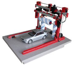
The car wash is a product from the company Staudinger GmbH. Staudinger makes educational models that can be controlled with a PLC.
The car wash has 6 inputs and 6 outputs. The portal can drive left and right. The horizontal brush can move up and down. The horizontal and vertical brushes can spin. There is detection at the begin and end of the portal, top / bottom detection for the vertical brush and a height detection for the car.
The car wash is sold in the Netherlands by the company Edutec. Normally the car wash is controlled with a Siemens LOGO! or a Moeler Easy PLC. [551]
Car wash controlled with a Commodore SX-64
On these Youtube videos you can see the car wash in action. The car wash is controlled with a Commodore SX-64 with a special interface. A SX-64 was chosen, but a VIC-20, C64, C128, Plus/4 or a Amiga is also possible.
On top of the car is a white band. This improves the height detection. The height detection works on the principle of light reflection.
Link
Link [552]
On top of the car is a white band. This improves the height detection. The height detection works on the principle of light reflection.
Link
Link [552]
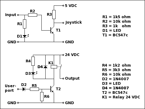
The interface schematic
 To control the car wash a interface is necessary.
One of the reasons is that the model needs a 24 VDC power supply and the Commodore C64 works with 5 VDC.
Also the current that a C64 can deliver is to small for controlling the model.
The upper part of the schematic is for reading the signals from the model in to the Commodore C64.
The lower part is for controlling the model from the C64.
The LED D1 shows the status of the input signal. The LED D3 shows the status of the output signal.
If a voltage of 0 VDC is applied to the input the LED D1 will not light up and the transistor T1 will be turned off. The signal at the joystick port will be a "1" via the "pull-up" resistor R3.
If a voltage of 24 VDC is applied to the input the LED D1 will light up and the transistor T1 will turned on. The signal at the joystick port will be an "0".
Remark: The signal from the input is inverted. This has to be considered when writing the program.
If the C64 user-port applies a voltage of 0 VDC the transistor T2 will be turned off and the relays K1 will also be turned off.
If the C64 user-port applies a voltage of 5 VDC the transistor T2 will be turned on, the relays K1 will be turned on and LED D3 will light up. [553]
The interface
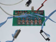
 On the picture you can see the interface. The red and black wires are for the (24 VDC) supply power. The joystick connector will supply the input signals to the Commodore C64. Via the user-port connector the model is controlled by the C64. The 37 pin D connector connects the interface to the model.
The interface uses the user-port and the joystick-port. This is done because the user-port has not enough inputs and outputs. The downside is that a number of keys on the keyboard are not usable any more. The joystick input signal are connected to the keyboard.
The complete schematic.
The inputs 5 and 6 (height detection) are read as one signal. The pro is that you need only 1 joystick connector.
On the picture a slightly different schematic is used. The relays on the interface are 12 VDC. This makes an extra voltage regulator necessary. [554]
The program
 To control the car wash software is needed for the Commodore C64.
The choice was made to write the program in BASIC, but machine language is also possible.
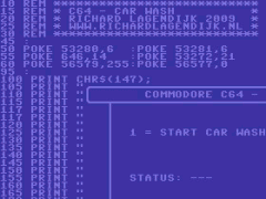
Click on the picture to view the whole BASIC program.
Inputs:
Address = 56320
Bit 0 = Portal at start position
Bit 1 = Portal at end position
Bit 2 = Brush top position
Bit 3 = Brush bottom position
Bit 4 = Height detection
Outputs:
Address = 56577
Bit 0 = Portal to start position
Bit 1 = Portal to end position
Bit 2 = Brush up
Bit 3 = Brush down
Bit 4 = Brush vertical on
Bit 5 = Brush horizontal on
The BASIC program in d64 format. [555]
Update: 2019-05-12 13:24:37